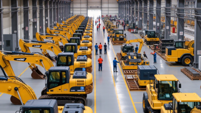
| Small equipment inside a workshop |
Up to 5 metric tonnes |
Approximately 1.0–2.5 m long; 0.8–1.8 m wide; 1.0–2.2 m high |
Usually compact, but the center of gravity may be high on vertical machines or cabinets |
Smooth concrete floor; short, straight route; limited height restrictions |
Toe jacks, low-profile machinery skates, pry bars, and manual or electric winches |
Use equipment with a combined rated capacity at least 25% above the verified load |
Confirm jack clearance, wheel or roller contact pressure, turning radius, and overhead obstructions |
| Medium machine relocation |
5–20 metric tonnes |
Approximately 2.0–5.0 m long; 1.5–3.0 m wide; 1.5–3.5 m high |
May have an offset center of gravity because of motors, transformers, tanks, or tooling |
Indoor concrete route with expansion joints, ramps, or minor changes in floor level |
Hydraulic toe jacks, machinery skates, synchronized hydraulic skidding systems, and controlled winching |
Check both total capacity and the capacity of each jack, skate, or skid point |
Calculate point loads, bridge floor joints where necessary, and control speed on ramps |
| Large industrial machine in a plant |
20–80 metric tonnes |
Approximately 4.0–10.0 m long; 2.5–5.0 m wide; 2.5–5.0 m high |
Often asymmetrical; the center of gravity should be established from drawings or a controlled lift plan |
Long indoor route; restricted aisle width; floor joints, trenches, ramps, or uneven surfaces may be present |
Hydraulic gantry, heavy-duty skidding system, powered transporters, or a combination of jacking and skidding equipment |
Use an engineered load-distribution plan; do not rely only on the machine's total weight |
Verify floor slab capacity, route width, turning clearances, lifting points, and emergency stop procedures |
| Very heavy transformer, press, or generator |
80–300 metric tonnes |
Approximately 5.0–15.0 m long; 3.0–6.0 m wide; 3.0–6.0 m high |
High or offset center of gravity is common; load tipping and lateral movement must be assessed |
Heavy-duty concrete or engineered transport route; limited access and high ground-bearing requirements |
Self-propelled modular transporter, hydraulic gantry, strand jack system, or engineered skid shoes |
Capacity must be checked for total load, axle or wheel-group loading, support reactions, and dynamic effects |
Use a stamped or approved lift-and-move plan where required; survey the route and confirm utility clearances |
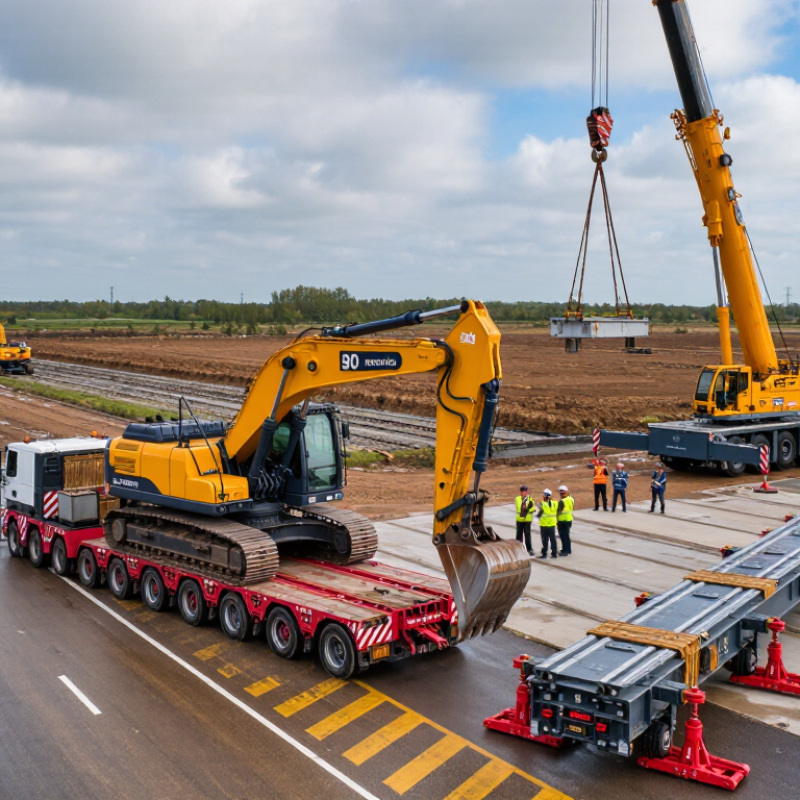
| Outdoor movement on a prepared hardstand |
10–100 metric tonnes |
Varies by machine; route width commonly needs to exceed the load width by a controlled clearance |
Wind, uneven loading, and attachment points can change the effective stability of the load |
Compacted gravel, asphalt, or concrete; weather and drainage can affect traction and ground strength |
Self-propelled transporter, modular trailer, heavy-duty skates on steel plates, or mobile crane support |
Check ground-bearing pressure and traction in addition to rated lifting or transport capacity |
Inspect weather conditions, slopes, drainage, overhead lines, surface settlement, and access for recovery equipment |
| Outdoor movement over compacted soil |
Up to approximately 50 metric tonnes, subject to ground verification |
Load dimensions and transporter footprint must be matched to the available route width |
Low-clearance loads may be stable, but soft ground can cause sudden tilt or settlement |
Variable soil strength; wet conditions can substantially reduce bearing capacity |
Tracked transporter, low-ground-pressure transporter, crane-assisted placement, or engineered steel roadways |
Equipment selection depends on verified allowable ground pressure, not only machine weight |
Conduct ground investigation; use mats or steel plates where necessary and stop work if rutting develops |
| Movement through a narrow doorway or aisle |
Typically up to 30 metric tonnes, depending on available clearance |
Measure the narrowest opening, aisle width, ceiling height, and turning envelope |
Load overhang and off-center weight can reduce clearance and stability during turns |
Smooth indoor floor with restricted maneuvering space |
Low-profile skates, hydraulic jacks, multidirectional skates, compact transporter, or temporary disassembly |
Use the lowest practical equipment height and maintain a documented clearance margin |
Measure actual dimensions, including rigging and protective packaging; check door strength and fire-control systems |
| Loading or unloading from a trailer |
5–150 metric tonnes, depending on trailer configuration |
Confirm load length, width, height, axle position, and tie-down locations |
Center of gravity must be aligned with the trailer's permitted loading zone |
Level loading area with adequate pavement strength and sufficient space for alignment |
Hydraulic gantry, mobile crane, self-propelled transporter, loading ramp, or hydraulic trailer |
Verify trailer payload, axle loads, ramp capacity, crane radius, and transporter capacity |
Control trailer deflection, secure the load against movement, and establish exclusion zones |
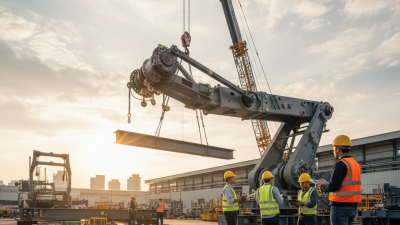
| Vertical lifting followed by horizontal positioning |
Any load requiring a controlled lift; commonly above 10 metric tonnes |
Consider lift height, headroom, rigging length, landing height, and final installation envelope |
Determine the true center of gravity and identify approved lifting lugs or structural lift points |
Restricted headroom, confined access, or sensitive finished floors may be present |
Hydraulic gantry, overhead crane, mobile crane, strand jack, jacking system, or skidding equipment |
Rated capacity must cover the load, rigging, lifting accessories, and any uneven load share |
Check lift-point ratings, sling angles, headroom, structural support, wind limits, and communication methods |
| Sensitive or precision equipment |
1–50 metric tonnes |
Dimensions may be compact, but vibration and tilt limits can be more important than size |
Protect delicate internal components; keep the load level within the manufacturer's transport limit |
Clean, level floor with controlled vibration and protection from shock, moisture, and contamination |
Air casters, low-vibration skates, powered transporter, shock-monitoring devices, and precision jacking systems |
Capacity must include an adequate margin while maintaining low contact pressure and controlled movement |
Review tilt limits, acceleration limits, shock indicators, environmental conditions, and final alignment requirements |
| Long or flexible load |
10–100 metric tonnes |
Usually longer than 10 m; width and height may be moderate but turning clearance is significant |
Deflection, torsion, and multiple support reactions must be considered along the load length |
Route may include turns, slopes, joints, or changes in elevation |
Modular transporter, multi-point hydraulic trailer, synchronized skidding system, or engineered support frame |
Check distributed support reactions and allowable bending stress at every support point |
Model the turning path, control synchronized movement, and protect the load from twisting or unsupported spans |
| Inclined route or ramp movement |
Up to approximately 50 metric tonnes, subject to traction and restraint calculations |
Load height and length affect stability and the required stopping distance |
High center of gravity increases the risk of sliding, tipping, or uncontrolled rollback |
Ramp gradient, surface friction, drainage, and edge protection are critical |
Powered transporter with independent braking, winch-assisted skidding, hydraulic jacking, or mechanical restraint |
Calculate pulling force, braking force, friction, and a secondary restraint method |
Do not rely solely on friction; confirm gradient, surface condition, anchorage strength, and escape routes |
| Restricted-access or low-headroom installation |
5–80 metric tonnes |
Low-profile equipment may be required; measure every obstruction along the route |
Load height, rigging height, and temporary supports must fit within the available envelope |
Confined room, low ceiling, narrow access, or limited ventilation |
Low-profile hydraulic jacks, skid shoes, compact gantry, strand jacks, or air casters |
Capacity, minimum operating height, stroke, and lateral stability must all be confirmed |
Prepare a three-dimensional route survey and verify ventilation, lighting, emergency access, and communication |
| Planning baseline for any heavy move |
Use the verified gross mass, not an estimate |
Record length, width, height, lifting points, support points, and transport envelope |
Locate the center of gravity and identify any liquid, battery, or removable component that changes it |
Verify floor or ground bearing capacity, gradients, obstacles, weather, and route condition |
Select equipment by rated capacity, geometry, maneuverability, control, and surface compatibility |
Apply the applicable local regulations, manufacturer instructions, and engineered safety factors |
Final equipment selection should be confirmed by a qualified lifting or transport engineer, especially for heavy, high, irregular, or high-consequence loads. |